PRODUCTS
- Home
- Coupling
- Flexible couplings
- Shaft coupling
- Universal joints
- Support
CONTACT US

CSF-A1 Type Locking Assembly TLK300
Model Number
Check below, custom
TLK, CSF-A1
- Phone : +86 13431039760
- Wechat : +86 13431039760
- Whatsapp : +86 13431039760
- Email : ella@apexcoupling.com
Product Description
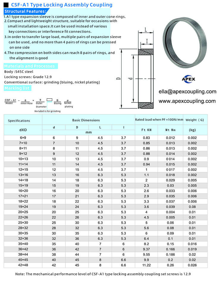
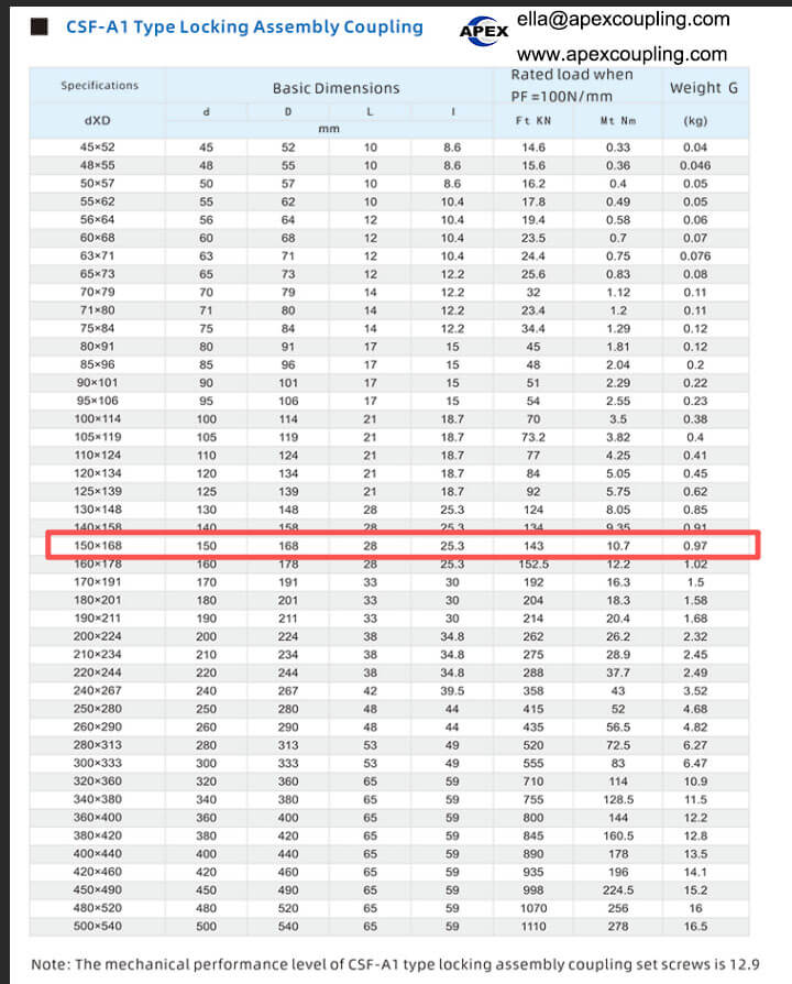
CSF-A1 Locking Assembly for Keyless Shaft-Hub Connections
Product Overview
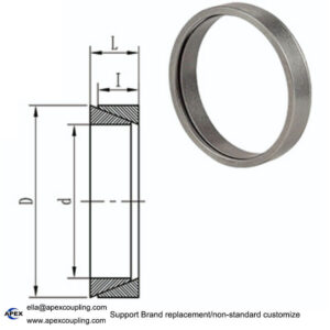
The CSF-A1 locking assembly is a mechanical shaft-hub locking device designed for keyless power transmission connections. It uses a clamping mechanism to secure the shaft and hub, providing an alternative to conventional keyed connections or interference-fit connections in compatible applications.
According to the supplied product information, the locking assembly features a compact, lightweight structure that is suitable for installations with limited radial space. Its inner and outer tapered components generate clamping pressure when the locking screws are tightened according to the specified installation procedure.
The CSF-A1 locking assembly is designed for applications requiring medium-low torque transmission, limited installation space and relatively straightforward installation. For applications involving higher loads, multiple expansion sleeve pairs may be considered if permitted by the specific design and manufacturer’s technical instructions.
Apex Coupling supports industrial power transmission components and customized supply according to confirmed technical requirements.
Key Features of the CSF-A1 Locking Assembly
1. Compact and Lightweight Design
The compact structure helps reduce radial space requirements around the shaft-hub connection. It is suitable for machinery where installation space is restricted and a conventional keyed connection may not be the preferred solution.
2. Keyless Shaft-Hub Connection
The locking assembly transfers torque through contact pressure between the connected components. This can eliminate the need for a conventional shaft key when the shaft, hub and locking assembly are designed for a compatible keyless connection.
Correct shaft and hub dimensions are essential for reliable operation.
3. Steel Construction
The supplied material information specifies S45C steel for the body. This steel is used in mechanical components requiring strength and durability.
The final mechanical properties depend on the manufacturing process, heat treatment, surface finish and applicable material specifications.
4. Grade 12.9 Locking Screws
The locking screws are specified as grade 12.9. Correct tightening torque and the recommended tightening sequence are important for achieving the intended clamping force.
Always follow the technical instructions for the exact model.
5. Medium-Low Torque Applications
The supplied product description identifies this locking assembly as suitable for medium-low torque applications. The allowable torque must be checked against the selected model’s technical data and the operating conditions of the equipment.
6. Surface Finish Options
The conventional surface finish is described as grinding, with bluing and nickel plating available as finish options according to the supplied information. Confirm the available finish and any special corrosion-resistance requirements when requesting a quotation.
7. Multiple Locking Elements for Higher Loads
The supplied description indicates that multiple expansion sleeve pairs may be used for applications requiring greater load capacity, subject to the specific design. The permissible number, arrangement and tightening procedure must be confirmed from the applicable technical documentation before installation.
Technical Specifications
| Parameter | Specification |
|---|---|
| Product name | CSF-A1 Locking Assembly |
| Product type | Keyless shaft-hub locking device |
| Design | Tapered locking components, according to supplied description |
| Body material | S45C steel |
| Locking screw grade | Grade 12.9 |
| Surface finish | Grinding; bluing or nickel plating options to be confirmed |
| Torque category | Medium-low torque, according to supplied description |
| Radial space requirement | Restricted radial encumbrance |
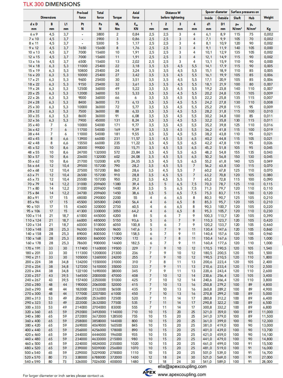
| Self-centering | Not self-centering, according to the supplied TLK300 description; confirm for CSF-A1 |
| Installation | Tighten screws gradually in a crossed sequence |
| Removal | Loosen the tightening screws; follow the model-specific release procedure |
| Customization | Confirm according to drawing and application requirements |
Technical note: The supplied information references CSF-A1, AL type and TLK300. Confirm the exact relationship between these designations before publishing the specification table as a final CSF-A1 datasheet. Rated torque, shaft diameter, hub dimensions, screw tightening torque and permissible axial load have not been provided.
Installation Instructions
Proper installation is important for achieving the intended clamping force and torque transmission performance.
Clean the contact surfaces. Clean the shaft and hub contact surfaces carefully before assembly.
Apply a light oil film if specified. The supplied instructions describe oil installation. Use only the lubricant and procedure approved for the exact model.
Position the locking assembly. Slide the locking components into the hub bore and insert the shaft according to the installation drawing.
Tighten the screws gradually. Tighten the locking screws in a regular, crossed sequence to the specified tightening torque.
Verify the assembly. Check the final position and alignment against the equipment requirements before operation.
The supplied instructions warn against using grease or oils containing molybdenum disulphide or high-pressure additives because these substances can reduce the friction coefficient. Always follow the manufacturer’s instructions for the specific product.
Dismantling Instructions
To remove the locking assembly, loosen the tightening screws according to the manufacturer’s prescribed procedure until the clamping force is released.
If removal is difficult, follow the designated release method for the specific locking assembly. Do not apply uncontrolled impact or force that could damage the shaft, hub or locking components.
If the component will be reused, inspect the locking surfaces, screws and threads for wear or damage before reinstallation.
Applications of the CSF-A1 Locking Assembly
Depending on the confirmed dimensions and load rating, a keyless locking assembly may be suitable for compatible shaft-hub connections in:
Industrial machinery
Manufacturing equipment
Pulleys and sprocket assemblies
Packaging machinery
Material handling systems
Mechanical power transmission equipment
Machinery repair and maintenance applications
The final selection should account for torque, rotational speed, shaft diameter, hub dimensions, operating loads and available installation space.
How to Select the Right Locking Assembly
Before ordering a CSF-A1 locking assembly, confirm the following:
Shaft diameter: Provide the nominal diameter and required tolerance.
Hub bore and outside diameter: Check the available mounting space and hub strength.
Torque requirement: Specify normal torque, starting loads and any shock loads.
Rotational speed: Confirm the intended operating speed.
Axial loads: Identify any axial forces acting on the connection.
Installation space: Check the available radial and axial dimensions.
Surface finish: Select the required finish according to the working environment.
Installation requirements: Confirm the specified tightening torque and lubrication procedure.
Model identification: Verify whether the required product is CSF-A1, AL type or another related series.
Technical drawing: Provide a drawing or sample when replacing an existing component.
These details help establish whether the selected locking assembly is suitable for the application.
CSF-A1 Locking Assembly Manufacturer – Apex Coupling
Apex Coupling supplies industrial power transmission components and supports customized manufacturing according to confirmed drawings and application requirements.
We welcome inquiries from machinery manufacturers, equipment integrators, distributors and industrial maintenance buyers looking for keyless shaft-hub locking solutions.
For a quotation, please provide the model number, shaft diameter, hub dimensions, required quantity and operating torque. Technical drawings are recommended for non-standard applications.
Contact Apex Coupling
Website: https://www.apexcoupling.com/
Email: ella@apexcoupling.com
WhatsApp: +86 13437856962
Frequently Asked Questions
What is a CSF-A1 locking assembly?
A CSF-A1 locking assembly is a mechanical device intended to secure a shaft and hub through a clamping connection. It can serve as an alternative to a keyed connection in compatible applications.
Does a locking assembly require a keyway?
A keyless locking assembly transfers torque through contact pressure rather than relying on a traditional key. Confirm that the shaft, hub and selected locking device are designed for a keyless connection.
What material is used for the CSF-A1 locking assembly?
The supplied product information specifies S45C steel for the body and grade 12.9 locking screws. Confirm the material and surface finish for the exact model before ordering.
Is the CSF-A1 self-centering?
The supplied description for TLK300 states that the locking assembly is not self-centering. Because the material also references CSF-A1 and AL type, confirm the centering characteristics for the exact product you intend to purchase.
How should the locking assembly be installed?
Clean the contact surfaces, follow the specified lubrication procedure, position the components correctly and tighten the screws gradually in a crossed sequence to the specified torque.
Can Apex Coupling supply customized locking assemblies?
Customized supply can be discussed according to the product design and manufacturing requirements. Provide the shaft diameter, hub dimensions, torque requirement and technical drawing for review.
keyless locking assembly
shaft hub locking assembly
locking assembly coupling
keyless shaft locking device
steel locking assembly
TKL Serie pls contact us. send us inquiry pls.
TLK 110, TLK 130, TLK 131, TLK 132, TLK 133/134, TLK 136, TLK 200, TLK 400/401, TLK 450/451, TLK 500, TLK 601/602/603, TLK 622/623/681/683
Product Show
CSF-A1 Type Locking Assembly