A Step-by-Step Guide
A rigid coupling is designed to connect two shafts tightly together, allowing for zero backlash and precise torque transmission. Its primary purpose is to hold the shafts in perfect alignment. Unlike flexible couplings, it does not compensate for any misalignment (parallel, angular, or axial). Any misalignment will lead to increased stress, vibration, bearing wear, and eventual failure.
Therefore, the selection process is meticulous and revolves around ensuring perfect alignment and understanding the application’s demands.
Step 1: Confirm that a Rigid Coupling is Suitable
First, ask: Do I need a rigid coupling?
Choose a rigid coupling if:
Precise Synchronization: The application requires zero backlash and perfect phasing between the two shafts (e.g., timing applications, dual-drive systems).
Perfect Alignment is Guaranteed: The machine is designed and built such that the two shafts can be and will be aligned with extreme precision during installation and will remain so during operation.
Shafts are Short and Supported: The shafts are supported by bearings close to the coupling, minimizing the chance of shaft deflection under load.
Avoid rigid couplings if:
There is any possibility of misalignment, even minor.
The machine frame or baseplate is not perfectly rigid and could flex.
The system is subject to thermal expansion that could change shaft positions.
There are vibrations or shock loads that need to be dampened.
Step 2: Define Your Application Requirements
Gather the following key parameters:
Torque Requirements:
Rated Torque: The continuous torque the coupling must transmit during normal operation.
Peak Torque: The maximum torque experienced during startup, jams, or shock loads. The coupling must withstand this without failing.
Service Factor: Account for the type of prime mover (motor) and driven equipment. A high-inertia crusher or compressor has a much higher service factor than a smooth-running pump or generator.
Shaft Sizes and Types:
Shaft Diameters: Precisely measure the diameters of both shafts. They can be the same or different.
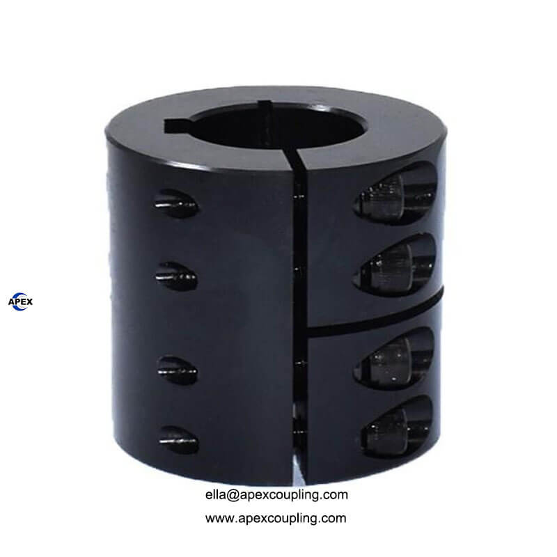
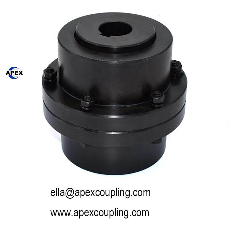
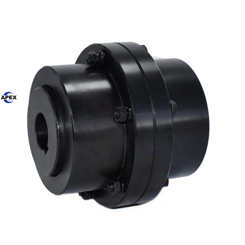
Keyway Dimensions: If using a key, you need the exact keyway width, depth, and tolerances (e.g., 1/4″ x 1/8″).
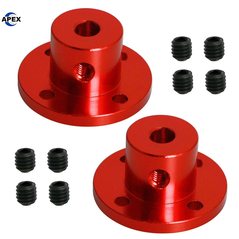
Set Screws: Determine the number, size, and placement of set screws if no key is used.
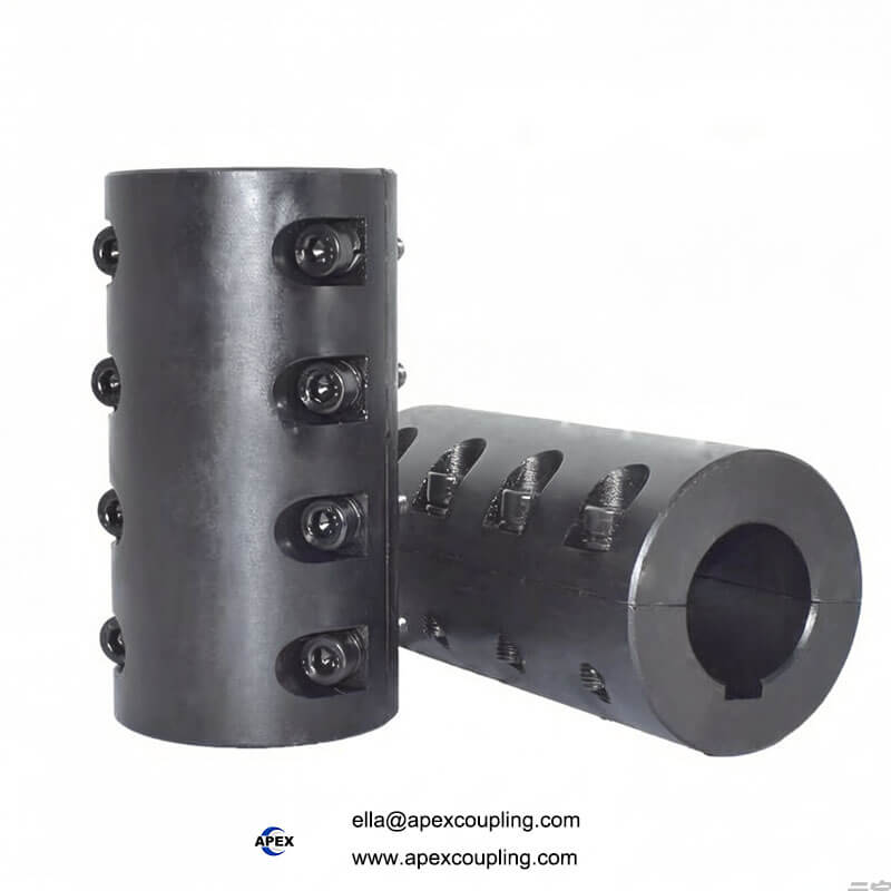
Tapered Bushings: Some rigid couplings use tapered bushings for a super-tight, keyless grip, which is excellent for high-torque applications.
Space and Physical Constraints:
Bore Size Range: Ensure the coupling can accommodate your shaft diameters.
Outside Diameter (OD): Check that the coupling will fit within the available space, with enough clearance for safety guards and tools.
Length: The overall length of the coupling must fit the gap between the two shaft ends.
Environmental Conditions:
Temperature: Standard couplings are for ambient temperatures. High-temperature applications require special materials (e.g., stainless steel).
Corrosion: In wet or chemical environments, choose materials like stainless steel or nickel-plated finishes.
Presence of Debris: Some designs (like solid sleeve couplings) offer better protection than flanged types.
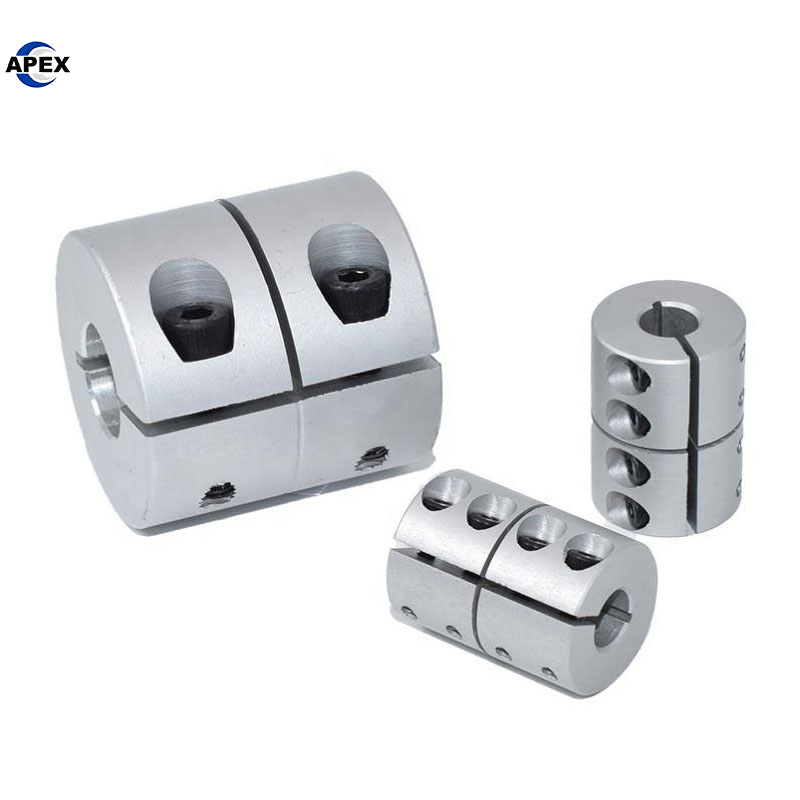
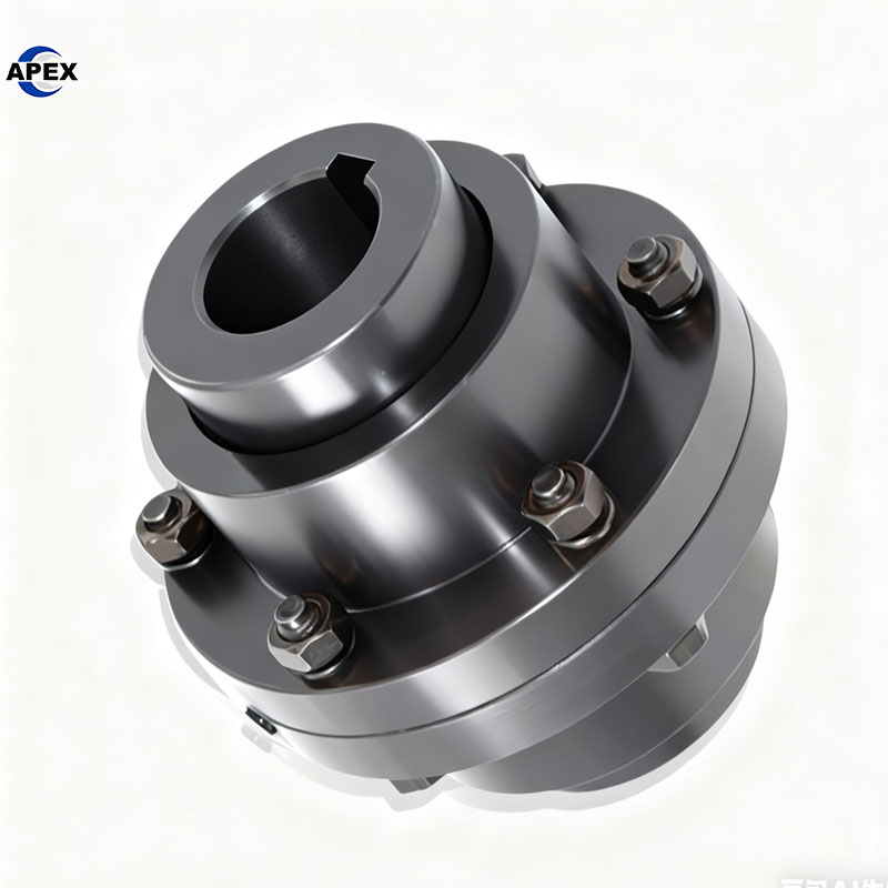
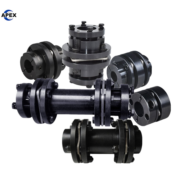
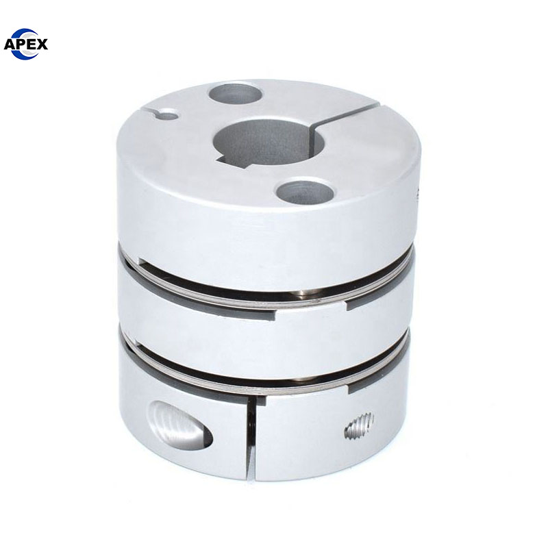
Step 3: Select the Type of Rigid Coupling
There are several common types, each with slight advantages:
Step 4: Material Selection
Steel: High strength and durability for most industrial applications.
Stainless Steel: For corrosive environments, food, marine, and pharmaceutical industries.
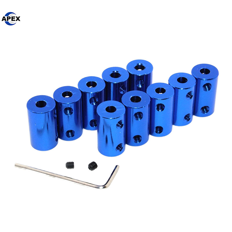
Aluminum: For applications where weight is a critical factor (e.g., robotics, aerospace), provided the torque requirements are met.
Cast Iron: Economical and good for dampening vibrations, but more brittle than steel.
Step 5: Installation and Maintenance Considerations
Ease of Installation: Flanged and clamp-style couplings are generally easier to install and remove than a tight-fitting sleeve coupling.
Balance: For high-speed applications, ensure the coupling is dynamically balanced by the manufacturer.
Lubrication: Most rigid couplings require no maintenance, but some flanged types with fitted bolts may need occasional check-ups.
Selection Checklist Summary
Answer these questions to make your final choice:
Is my system perfectly aligned and will it stay that way? (If yes, proceed.)
What is my maximum torque (including peaks)? (Find a coupling with a torque rating above this value.)
What are the diameters of my two shafts? (Find a coupling with a matching bore range.)
Do I need a keyway, set screws, or a keyless clamp? (Select the connecting method.)
What are the space limitations (OD, length)? (Check the coupling’s dimensions.)
What is the operating environment? (Choose the appropriate material.)
How easy does it need to be to install and remove? (Choose the type accordingly.)
By systematically following these steps, you can confidently select a rigid coupling that will provide reliable, precise, and efficient power transmission for your application.