Step Diaphragm Coupling Selection Guide – DST Series for Servo Motors & Automation
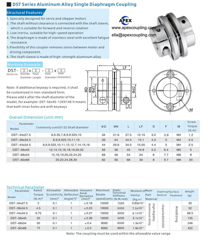
Step diaphragm couplings (also known as stepped disc couplings) represent an advanced evolution of single diaphragm coupling design. Featuring a unique step (stepped) configuration, they offer enhanced stress distribution and extended service life compared to standard flat diaphragm couplings. With zero backlash, high torsional rigidity, and low inertia, they are the preferred choice for servo motors, stepper motors, encoders, and precision automation applications.
This guide explains how step diaphragm couplings work, the advantages of the stepped design, and how to select the right model for your application.
1. What Is a Step Diaphragm Coupling?
A step diaphragm coupling (also called a stepped single diaphragm coupling) consists of:
Two aluminum hubs – high-strength aluminum alloy with anodized finish
A single stainless steel diaphragm – 304 stainless steel for fatigue resistance
A step (stepped) design – additional space for the diaphragm to flex
The step design creates additional space for the diaphragm to flex during operation, dispersing concentrated stress and延缓 the onset of fatigue cracks. This significantly extends the service life of the coupling compared to standard flat diaphragm designs.
💡 The step design is a key differentiator of the DST series, providing longer service life and more reliable performance under repeated cyclic loads.
2. Step Design Advantage – Why It Matters
The step (stepped) design offers several key advantages over standard flat diaphragm couplings:
| Advantage | Benefit |
|---|---|
| Enhanced Stress Distribution | Additional space for diaphragm flexing – disperses concentrated stress |
| Extended Service Life | Reduced stress concentration –延缓 fatigue crack propagation |
| Superior Misalignment Compensation | Smoother flexing – improved misalignment compensation |
| More Reliable Performance | Consistent performance under repeated cyclic loads |
💡 Step designs are particularly beneficial for applications with frequent starting, stopping, and reversing, where the diaphragm is subjected to repeated stress cycles.
3. Key Advantages of Step Diaphragm Couplings
| Advantage | Benefit |
|---|---|
| Zero Backlash | No rotational clearance – precise positioning for encoders and servo motors |
| High Torsional Rigidity | Accurately controls shaft rotation – enables high-precision control |
| Low Inertia | Lightweight aluminum design – ideal for high-speed operation up to 10000 RPM |
| Maintenance-Free | No lubrication required – reduces downtime |
| 304 Stainless Steel Diaphragm | Excellent fatigue resistance and corrosion resistance – long service life |
| Zero-Clearance Shaft Connection | Suitable for positive and negative rotation – identical clockwise and counterclockwise characteristics |
| Step Design | Enhanced stress distribution – longer service life |
4. Materials – Why Aluminum + 304 Stainless Steel?
The DST series uses a combination of high-strength aluminum alloy for the hubs and 304 stainless steel for the diaphragm:
| Component | Material | Benefits |
|---|---|---|
| Hubs | Aluminum alloy | Lightweight, low inertia, corrosion-resistant, anodized finish |
| Diaphragm | 304 stainless steel | Excellent fatigue resistance, corrosion resistance, long service life |
5. Applications Where Step Diaphragm Couplings Excel
| Industry | Application | Why DST? |
|---|---|---|
| Servo Motors | High-precision motion control | Zero backlash, high rigidity |
| Stepper Motors | Precision positioning | Zero backlash, low inertia |
| Encoders | Position feedback systems | Zero backlash, accurate signal transmission |
| CNC Machines | Feed drives, positioning systems | High precision, zero backlash |
| Laser Cutting | Precision positioning | Zero backlash, high rigidity |
| Robotics | Joint drives | Zero backlash, low inertia |
| Lead Screws | Linear motion systems | Zero backlash, precise positioning |
6. How to Select the Right Step Diaphragm Coupling
Step 1: Determine Your Torque Requirement
Calculate the torque your application requires.
Select a coupling with adequate torque capacity.
Step 2: Determine Single or Double Diaphragm
Single diaphragm (DST): For angular and axial misalignment, space-limited applications.
Double diaphragm: For applications requiring radial misalignment compensation.
Step 3: Match Shaft Diameters
Measure your shaft diameters.
Select a model with a bore range that accommodates your shafts.
H7 bore tolerance is recommended for precision fit.
Step 4: Consider Space Constraints
Measure available space for the coupling (outer diameter and length).
DST series offers sizes from 34mm OD.
Step 5: Evaluate Misalignment
Determine the expected angular and axial misalignment.
Single diaphragm couplings compensate for angular and axial misalignment.
Step 6: Consider Speed Requirements
Verify the coupling’s maximum speed exceeds your operating speed.
DST series offers speeds up to 10000 RPM.
Step 7: Consider Keyway Requirements
For applications requiring keyways, add “K” to the model number.
Example: DST-56×45-12K×14K – both bores with keyways.
7. Real‑World Example – CNC Machine Upgrade
A CNC machine manufacturer was experiencing position errors on a high-speed machining center due to backlash in their existing coupling. The coupling also suffered from premature fatigue failure due to repeated stress cycles.
They switched to Apex Coupling DST step single diaphragm coupling (aluminum hubs, 304 stainless steel diaphragm, step design, zero backlash). Results:
Position errors eliminated – zero backlash
Service life extended – step design enhanced stress distribution
Maintenance eliminated – no lubrication required
Accuracy improved – H7 precision bore
8. Installation & Maintenance Tips
Clean shafts – Remove oil, grease, and debris before installation.
Check alignment – Even with misalignment compensation, keep within recommended limits.
Tighten clamping screws evenly – Use a torque wrench in a star pattern.
No lubrication required – Coupling is maintenance-free.
Periodic inspection – Check for wear, cracks, or deformation in the diaphragm.
Keep clean – Remove dust and debris to prevent premature wear.
Keyway option – For keyway applications, ensure proper key fit.
9. Selection Checklist
- □
Type: DST – step single diaphragm coupling
- □
Structure: Single diaphragm – for angular and axial misalignment
- □
Material: Aluminum hubs + 304 stainless steel diaphragm
- □
Backlash: Zero backlash – precision applications
- □
Bore: H7 tolerance – match your shaft diameters
- □
Keyway: Add “K” if required (e.g., DST-56×45-12K×14K)
- □
Fastening: Clamping screw – secure, even clamping force
- □
Misalignment: Angular and axial – verify capacity
- □
Speed: Up to 10000 RPM – match your motor speed
- □
Maintenance: Maintenance-free – no lubrication
- □
Application: Servo motors, stepper motors, encoders, CNC machines
10. Conclusion
The DST step single diaphragm coupling from Apex Coupling offers the perfect combination of zero backlash, high torsional rigidity, low inertia, and extended service life for precision motion control applications. With aluminum alloy construction, 304 stainless steel diaphragm, step design for enhanced stress distribution, clamping screw fastening, and H7 bore precision, it is the ideal solution for servo motors, stepper motors, encoders, CNC machines, and precision automation.
👉 Need a step diaphragm coupling for your precision application? Contact us with your model, bore, and torque requirements.
Inquiry now:
ella@apexcoupling.com
Step diaphragm coupling selection guide
Single diaphragm coupling guide
Zero backlash coupling selection
Servo motor coupling
Encoder coupling guide
Aluminum flexible coupling
DST series coupling guide