PRODUCTS
- Home
- Coupling
- Flexible couplings
- Shaft coupling
- Universal joints
- Support
CONTACT US
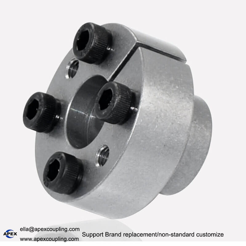
FL-F Thin Wall Locking Assembly | Keyless Shaft-Hub Connection
Model Number
Check below, custom
Z11-8*15
Z11-15*24
Z11-24*34
Z11-9*16
Z11-16*24
Z11-25*34
Z11-10*16
Z11-18*26
Z11-28*39
Z11-11*18
Z11-19*27
Z11-30*41
Z11-12*18
Z11-20*28
Z11-14*23
Z11-22*32
- Phone : +86 13431039760
- Wechat : +86 13431039760
- Whatsapp : +86 13431039760
- Email : ella@apexcoupling.com
Product Description
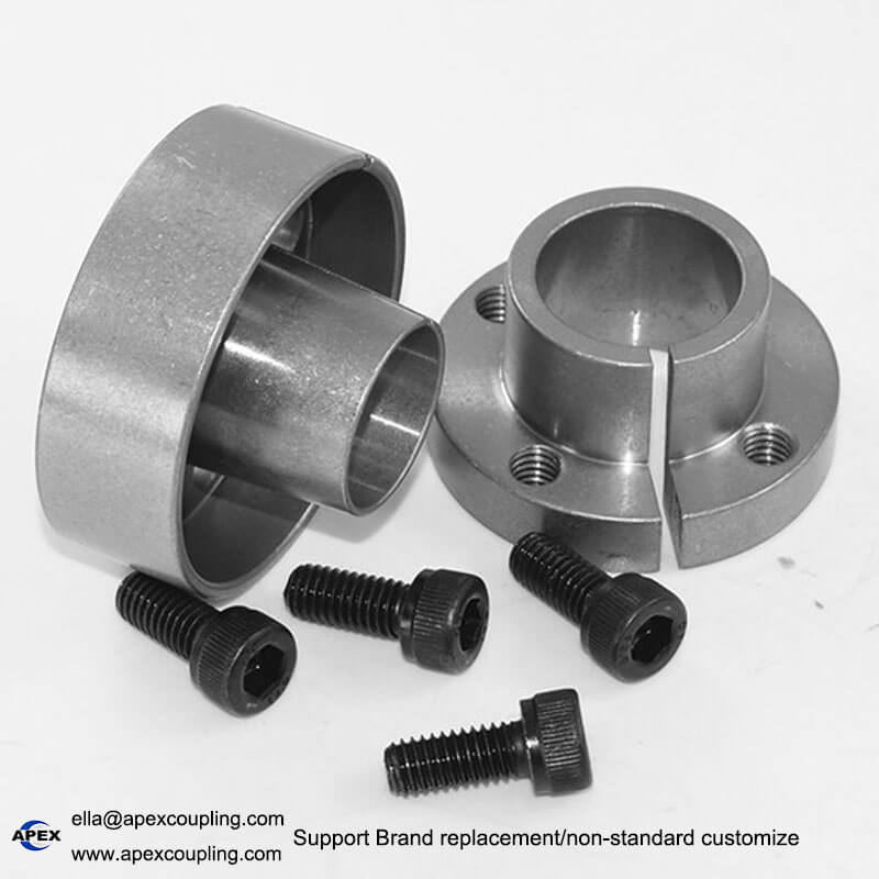
FL-F Thin Wall Locking Assembly
Compact Keyless Shaft-Hub Connection | 45# Steel | High-Strength Screws | Custom Manufacturing
The FL-F thin wall locking assembly is a compact keyless shaft-hub connection device designed for industrial power transmission applications where installation space is limited. Made from 45# steel and equipped with high-strength locking screws, this locking assembly helps secure compatible shafts and hubs through clamping force and friction.
With a small difference between its inner and outer diameters, the FL-F locking assembly supports space-saving mechanical designs. Its clamping structure helps maintain shaft-hub positioning during tightening and can reduce relative movement when the connection is correctly selected and installed.
Apex Coupling provides standard and customized locking assemblies for machinery manufacturers, distributors, and OEM customers. Contact us with your shaft dimensions, hub bore, installation space, and operating requirements for product selection.
Key Features of the FL-F Locking Assembly
1. Compact Thin Wall Design
The FL-F thin wall locking assembly is designed for applications with limited radial installation space. Its compact dimensions help engineers integrate a keyless shaft-hub connection into space-constrained mechanical systems.
2. 45# Steel Construction
The locking assembly is made from 45# steel. The material and specified heat-treatment process should be confirmed for the selected production batch and application requirements.
3. Secure Keyless Connection
The FL-F locking assembly creates a friction-based connection between compatible shaft and hub components. In suitable designs, it can eliminate the need for a conventional keyway and simplify machining and assembly.
4. Stable Positioning During Tightening
The locking structure is designed to help maintain the relative position of the shaft and hub during installation. Correct component tolerances and installation procedures are important for achieving the required alignment and connection performance.
5. High-Strength Locking Screws
High-strength screws provide the clamping force required for a secure connection. Use the specified tightening sequence and torque for the selected model rather than applying an assumed value.
6. Easy Installation and Removal
The FL-F locking assembly can be installed by tightening the locking screws according to the manufacturer’s instructions. Normal installation does not require hammering. The assembly can be removed for maintenance using the designated release procedure.
7. Surface Treatment Options
Standard surface finishing and optional treatments may be available, including black oxide, nickel plating, zinc plating, and phosphating. Confirm the available finish and corrosion-resistance requirements when placing an order.
8. OEM and Customization Support
Apex Coupling supports non-standard customization according to customer drawings and application requirements. Please provide the shaft diameter, hub bore, installation space, required torque, and operating conditions for technical review.
FL-F Thin Wall Locking Assembly Specifications
| Parameter | Specification |
|---|---|
| Product Name | FL-F Thin Wall Locking Assembly |
| Model | FL-F |
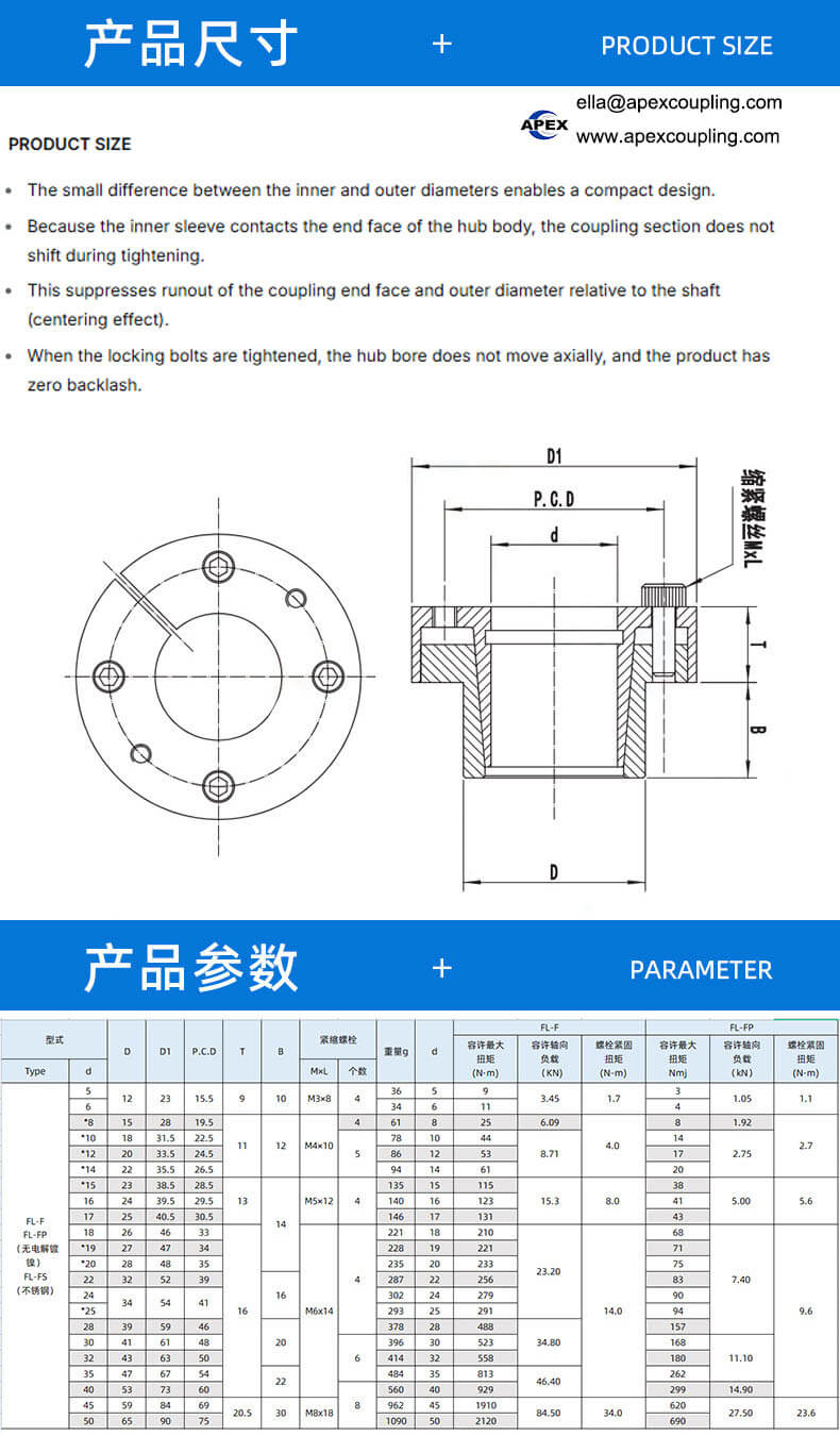
| Example Model | FL-F-12×5 |
| Example Outer Diameter | 12 mm |
| Example Inner Diameter | 5 mm |
| Example Length | Not specified; confirm by drawing |
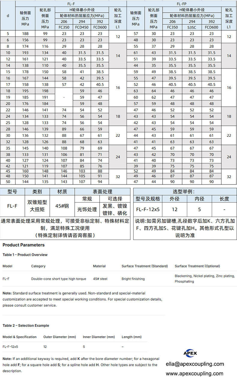
| Material | 45# steel |
| Connection Type | Keyless shaft-hub locking assembly |
| Fasteners | High-strength locking screws |
| Standard Surface Finish | Conventional finish, subject to confirmation |
| Optional Surface Treatments | Black oxide, nickel plating, zinc plating, phosphating, subject to availability |
| Customization | Available upon technical review |
Technical note: The supplied dimensional example identifies an outer diameter of 12 mm and an inner diameter of 5 mm. The length, allowable torque, axial load, tightening torque, and maximum speed have not been provided. Please request the detailed drawing and model-specific performance data before final selection.
How Does a Thin Wall Locking Assembly Work?
A thin wall locking assembly connects a shaft and hub by generating clamping pressure through its locking mechanism. The resulting frictional force transfers torque between the connected components without relying on a traditional shaft key.
Compared with a conventional keyed connection, a keyless locking assembly can reduce keyway machining and simplify positioning during assembly. The compact design of the FL-F series is particularly relevant when available installation space is restricted.
Actual torque capacity, alignment accuracy, and resistance to movement depend on the specific locking assembly design, shaft and hub tolerances, contact surfaces, and correct installation.
Typical Applications
The FL-F thin wall locking assembly can be considered for compatible shaft-hub connections in:
CNC machine tools and precision machinery
Food and packaging machinery
Metallurgical equipment
Photovoltaic manufacturing equipment
Woodworking machinery
Chemical processing equipment
Semiconductor manufacturing equipment
Printing machinery
Industrial automation and transmission systems
Railway-related equipment
For applications involving frequent forward and reverse rotation, shock loads, or high operating speeds, confirm the model-specific performance ratings and required safety factor before ordering.
Installation and Removal
Installation Procedure
Confirm that the shaft diameter, hub bore, and locking assembly dimensions match the selected model.
Inspect and clean the shaft, hub, and mating contact surfaces.
Position the locking assembly according to the manufacturer’s technical drawing.
Tighten the screws gradually in the specified sequence using the recommended tightening torque.
Check alignment and verify the connection according to the machine manufacturer’s procedure before operation.
Removal and Maintenance
Stop the machine and safely isolate all power sources.
Release stored mechanical energy and support the connected components where necessary.
Loosen the locking screws and follow the manufacturer’s release procedure.
Inspect the assembly, shaft, hub, and screws for wear or damage before reuse.
Do not use uncontrolled hammering or exceed the specified tightening torque. Proper installation is essential for reliable operation.
FL-F Locking Assembly vs. Traditional Keyed Connections
| Feature | FL-F Locking Assembly | Traditional Keyed Connection |
|---|---|---|
| Torque Transfer | Friction-based clamping | Key and keyway engagement |
| Keyway Machining | Not required in compatible designs | Usually required |
| Space Requirements | Compact design for suitable applications | Depends on shaft, key, and hub geometry |
| Assembly Positioning | Adjustable before final tightening, depending on design | Requires keyway alignment |
| Maintenance | Can be disassembled and inspected | Key and keyway require inspection |
The most suitable connection depends on the required torque, shaft dimensions, available space, operating conditions, and maintenance requirements.
Why Choose Apex Coupling?
Apex Coupling supplies industrial couplings and keyless shaft-hub connection components for OEMs, distributors, and machinery manufacturers.
Factory-direct manufacturing and supply
Standard and non-standard customization
45# steel product options
Support for drawing-based inquiries
Technical assistance with model selection
Solutions for industrial power transmission applications
Request a Quote for the FL-F Thin Wall Locking Assembly
Looking for a compact FL-F locking assembly for your machinery?
Please provide the shaft diameter, hub bore, required installation space, operating torque, rotational speed, application details, and order quantity. If you are replacing an existing locking device, include the original model number and dimensional drawing so we can check the relevant specifications.
Apex Coupling
Website: https://www.apexcoupling.com/
Email: ella@apexcoupling.com
WhatsApp: +86 13437856962
thin wall locking assembly, keyless shaft locking device, shaft hub locking assembly, thin wall taper locking assembly, FL-F keyless locking device
Product Show
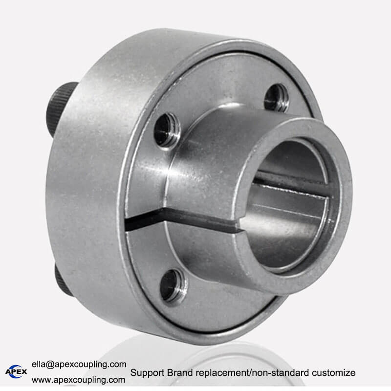
FL-F locking assembly