Rigid Coupling Selection Guide: How to Choose an Aluminum High‑Torque Coupling
In high‑precision servo/stepper motor drive systems, the coupling directly affects positioning accuracy, dynamic response, and service life.
Many engineers struggle between “rigid coupling” and “flexible coupling”. This article explains how to select an aluminum high‑torque rigid coupling and when it is the only correct choice.
1. Rigid vs Flexible Coupling – Key Differences
| Feature | Rigid Coupling | Flexible Coupling |
|---|---|---|
| Zero Backlash | ✅ Absolute | ❌ Some have backlash |
| Misalignment absorption | ❌ No | ✅ Yes (angular/parallel) |
| Rigidity | Extremely high | Low to medium |
| Best for | High precision, short spans, aligned shafts | Misaligned shafts, vibration damping |
Conclusion: If your machine requires no power/motion loss and shafts can be precisely aligned, a rigid coupling is the best solution.
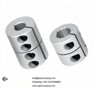
2. Why Choose an Aluminum High‑Torque Rigid Coupling?
a) Zero Backlash – No Lost Motion
The one‑piece metal design eliminates any clearance, providing instant response in forward/reverse rotation – ideal for CNC, semiconductor equipment, etc.
b) High Rigidity – Efficient Torque Transmission
Torsional stiffness is far higher than jaw or bellows couplings. Handles peak torque loads without wind‑up.
c) Aluminum Advantages
Low inertia – perfect for high acceleration/deceleration
Corrosion resistant – suitable for humid or chemical environments
Good heat dissipation – lower temperature rise at high speeds
d) Clamp‑Type Mounting – Shaft Friendly
Unlike setscrew types, the clamp design does not damage shafts and provides even, high clamping force.
3. 5 Key Parameters for Rigid Coupling Selection
Torque – coupling rated torque ≥ 1.5 × motor rated torque
Bore range – must match motor shaft and lead screw diameters
Max speed – should exceed motor maximum speed
Installation space – check length and outer diameter clearance
Alignment accuracy – rigid couplings require radial runout <0.02mm and angular <0.05°
4. The Most Overlooked Issue: Shaft Alignment
Because a rigid coupling cannot absorb any misalignment, you must:
Use a dial indicator or laser alignment tool to check coaxiality
Pre‑tighten screws, rotate one full turn to confirm no binding, then torque to specification
Never hammer the coupling onto shafts – it may damage bearings
✅ Tip: Mount a dial indicator on both sides of the coupling to measure radial and axial runout.
5. Real‑World Example: Solar Tracking Lead Screw Drive
Customer requirement: Zero backlash, outdoor corrosion resistance, torque 12 N·m for solar tracker lead screw.
Solution: DXC‑32 aluminum high‑torque rigid coupling, bores 12mm/14mm, stainless steel screws. After two years outdoors – no loosening or backlash.
6. Summary – When to Definitely Choose a Rigid Coupling?
Your machine demands extremely high repeatability (semiconductor, machine tools)
Motor and load shafts are close together and can be precisely aligned
You need maximum torque transfer efficiency with no damping requirement
Environment has corrosion or temperature variation (aluminum outperforms steel)
Still unsure? Contact Apex Coupling for free sizing assistance + 3D drawings.
how to choose a coupling
aluminum coupling manufacturer
zero backlash coupling
servo motor coupling selection
coupling alignment