Common Couplings in Mechanical Design and the Selection Process
In custom automation equipment, the connection method between a motor and its load critically influences the system’s transmission accuracy, lifespan, noise, and maintenance cost. The coupling is the most common connecting component, and different types are designed to adapt to varying speeds, torque levels, misalignment, and application scenarios. For many engineers, the key to selection is not memorizing part numbers but understanding the core characteristics of each coupling type and following a logical selection process.
1. Classification and Characteristics of Common Couplings
Flexible Coupling
These couplings incorporate elastic elements to absorb vibration, compensate for misalignment, and protect connected equipment.
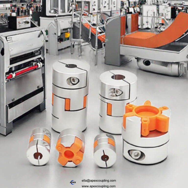
Spider/Jaw Coupling: Features two jaw hubs and a central elastomer spider. It’s cost-effective, simple in structure, and can compensate for small radial and angular misalignment. Ideal for servo motors, stepper motors, and light-duty transmission. Elastomers of varying hardness offer different torque capacities and damping effects. Typical Application: Lead screw drives, light-duty conveyors, positioning systems.
Beam Coupling: Offers better vibration damping but slightly lower torsional rigidity. Used in applications with significant shock loads.
Pin & Bush Coupling: Uses rubber bushes to carry load, providing stronger vibration absorption and greater misalignment capacity than spider types. Application: General-purpose connections between motors and gearboxes.
Rigid Coupling
This category has no elastic elements and cannot compensate for misalignment. Its primary advantage is the highest possible torsional rigidity, making it ideal for high-precision positioning.
Clamp Coupling / Rigid Shaft Coupling: Offers extremely high torque transmission rigidity and near-zero backlash, perfect for high-accuracy positioning. Crucial Note: It demands near-perfect shaft concentricity; otherwise, bearing loads increase significantly. Typical Application: High-precision linear modules, internal drive shafts in instrumentation. For engineers seeking uncompromising precision, ApexCoupling’s rigid coupling and clamp coupling solutions are engineered for these demanding scenarios.
Diaphragm Coupling
Compensates for misalignment through the flexing of thin metal diaphragms.
Characteristics: Zero backlash, high-speed capability, long life, no lubrication, high precision.
Ideal For: High-speed servo systems, precision positioning, applications requiring low rotational inertia.
Limitation: Higher cost, not suitable for high shock loads.
Bellows Coupling
Uses a metallic bellows to elastically compensate for misalignment.
Characteristics: Strong angular and axial compensation, zero backlash, fast response.
Application: High-precision servos, optical equipment, precision machine tools.
Limitation: Poor shock resistance, requires reasonable installation concentricity.
Gear Coupling
Transmits torque through the meshing of internal and external gear teeth.
Characteristics: Extremely high load capacity, can compensate for significant misalignment.
Application: Heavy-duty machinery, metallurgical equipment, hoisting equipment.
Limitation: Requires lubrication, complex structure, not suitable for high-speed servo systems.
Oldham Coupling
Transmits force through a central sliding disc, accommodating large parallel misalignment.
Characteristics: High torque capacity, good misalignment compensation.
Limitation: Has inherent backlash, unsuitable for precision transmission. Primarily for general mechanical drives.
2. The Coupling Selection Process
Step 1: Calculate Torque Based on Load
Determine the required torque. For a motor:
Input Torque T = 9550 × Power (kW) / Speed (rpm)
For a ball screw, calculate equivalent torque:T = Thrust Force (F) × Lead (L) / (2π × Efficiency η)
A safety factor of 1.5 to 3 is typically applied to the calculated torque when selecting the coupling.
Step 2: Identify Load Type and Application Scenario
Match the coupling type to the application’s primary demands:
Light Load, High Positioning Accuracy: Choose Bellows, Diaphragm, or Rigid Couplings.
Medium Load, Servo/Stepper, Standard Ball Screw: Choose Spider Coupling.
Heavy Load, High Shock: Choose Pin & Bush Coupling.
Heavy Duty, Low Speed, Large Misalignment: Choose Gear Coupling.
High Speed, High Response: Choose Diaphragm or Bellows Coupling.
Step 3: Confirm Shaft Dimensions and Installation Space
Verify the parameters of the motor, gearbox, and load shafts:
Shaft Diameter (Must match exactly).
Shaft Type (Plain, keyed, or for clamping).
Available installation length.
Maintenance requirements (e.g., lubrication-free).
Important: Servo motors typically use clamp-style couplings, not keyed types.
Step 4: Verify Misalignment Compensation Capability
Consider compensation needed for assembly errors and thermal expansion:
Radial, axial, and angular misalignment.
For example, ball screw drives require minimal angular error (suitable for spider couplings), while high-precision modules demand zero backlash (requiring diaphragm, bellows, or a high-quality rigid shaft coupling).
3. Common Selection Case Studies
Case 1: Servo Motor driving a Ball Screw
Requirements: High positioning accuracy, fast response, high torsional rigidity.
Selection: Diaphragm Coupling or high-hardness Spider Coupling.
Reason: Zero backlash and stable performance.
Case 2: Stepper Motor driving a Light-Duty Belt Module
Requirements: Medium precision, cost-effective.
Selection: Spider Coupling.
Reason: Good misalignment compensation, low cost, handles light shock loads.
Case 3: High-Precision Linear Module
Requirements: Ultra-high repeatability, zero backlash, maximum stiffness.
Selection: ApexCoupling Rigid Coupling or Clamp Coupling.
Reason: Provides absolute torsional rigidity and perfect synchronization where shafts are precisely aligned, eliminating any chance of lost motion.
Case 4: High-Speed Spindle Equipment
Requirements: High rotational speed, zero clearance.
Selection: Diaphragm Coupling.
Reason: Excellent dynamic balance and high-speed capability.
4. Conclusion and Recommendation
The essence of coupling selection lies in answering three core questions:
Does the application require misalignment compensation?
What are the precision and backlash requirements?
What is the nature of the load torque and shock?
In summary: Prioritize diaphragm, bellows, or spider couplings for servo motors; pin & bush or gear couplings for general motors; rigid shaft couplings for high-precision positioning where alignment is controlled; and gear couplings for heavy-duty, low-speed applications.

Engineer with Confidence Using ApexCoupling
Selecting the right component is pivotal to your design’s success. At ApexCoupling, we provide not just parts, but reliable transmission solutions. Our product range is designed to meet the stringent demands of modern automation:
For Unmatched Precision: Our rigid couplings and clamp couplings offer the ultimate in torsional stiffness for critical positioning applications.
For Flexible Performance: We supply a wide array of flexible couplings, including durable spider and diaphragm types.
For Every Application: From standard 3/4 rigid coupling sizes to custom rigid shaft couplings, we have the solution.
Don’t let the connection be the weakest link in your design.
Optimize your mechanical design with the right coupling. Explore ApexCoupling’s comprehensive range of high-performance rigid couplings, flexible couplings, and other drive solutions. Visit our website or contact our technical support team today for expert guidance on your specific application.