PRODUCTS
- Home
- Coupling
- Flexible couplings
- Shaft coupling
- Universal joints
- Support
CONTACT US
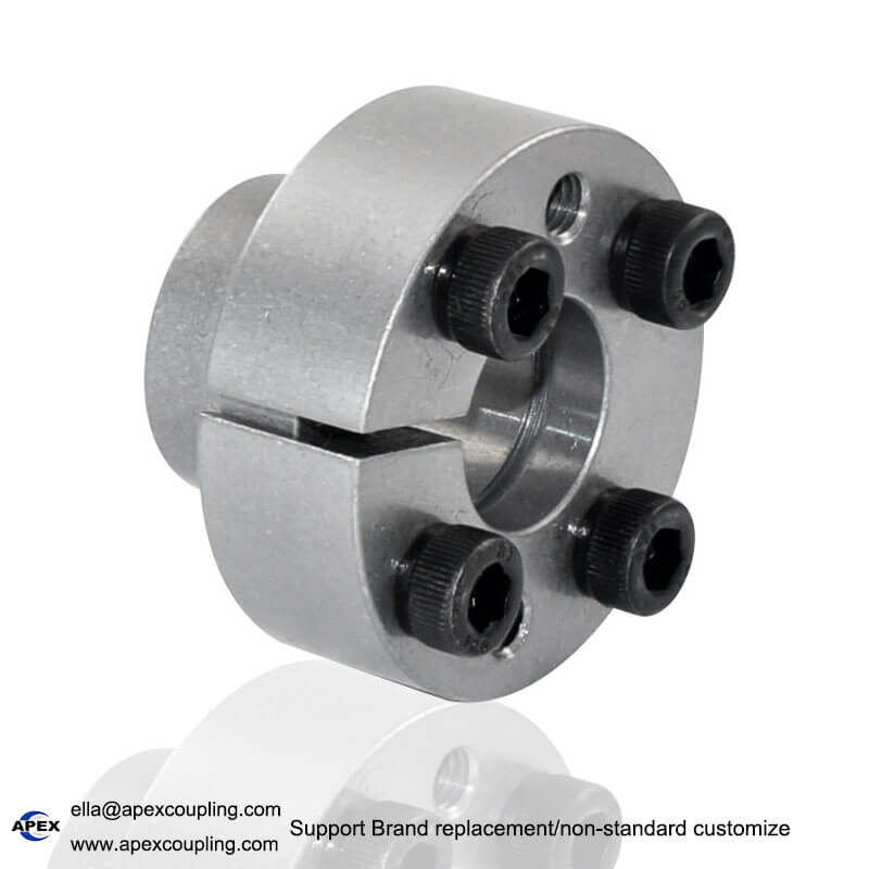
FL-F Thin-Wall Taper Locking Assembly
Model Number
Check below, custom
MLR5*12
MLR15*23
MLR22*32
MLR6*12
MLR16*24
MLR24*34
MLR8*15
MLR17*25
MLR25*34
MLR10*18
MLR18*26
MLR28*39
MLR12*20
MLR19*27
MLR14*22
MLR20*28
- Phone : +86 13431039760
- Wechat : +86 13431039760
- Whatsapp : +86 13431039760
- Email : ella@apexcoupling.com
Product Description
FL-F Thin-Wall Locking Assembly for Shaft-Hub Connections
Product Overview
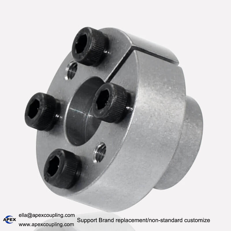
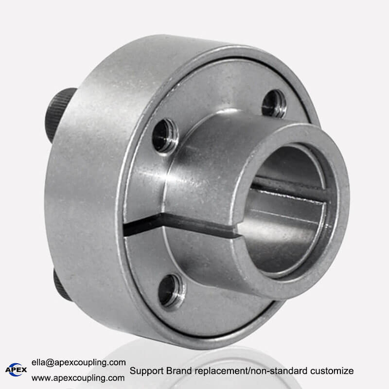
The FL-F thin-wall locking assembly is a mechanical locking component designed to secure a shaft and hub through a clamping connection. Its compact structure makes it suitable for applications where installation space is limited and a reliable shaft-hub connection is required.
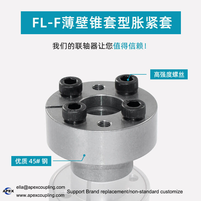
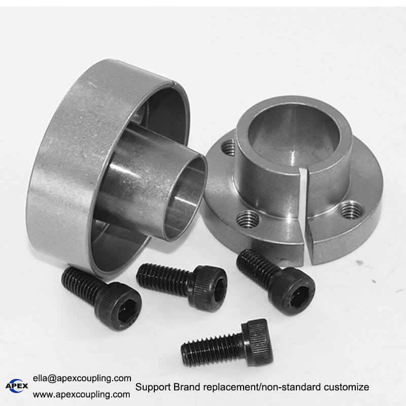
Manufactured from 45# steel according to the supplied product information, this thin-wall locking assembly uses high-strength tightening bolts to generate clamping force between the connected components. The design helps transmit torque through contact pressure rather than relying solely on a traditional keyed connection.
The FL-F series is intended for industrial power transmission systems where compact dimensions, accurate positioning and convenient assembly are important. Depending on the selected design, the locking assembly can help reduce relative movement between the shaft and hub during installation.
Apex Coupling supports customized dimensions and OEM supply according to confirmed technical drawings and application requirements.
Key Features of the FL-F Thin-Wall Locking Assembly
1. Compact Thin-Wall Structure
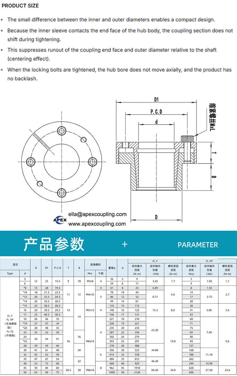
The small difference between the inner and outer diameters supports a compact shaft-hub connection design. This can be useful when installation space is limited or when a large locking component would interfere with surrounding machine parts.
2. 45# Steel Construction
The supplied product information specifies 45# steel with heat-treatment processing. The final mechanical properties depend on the manufacturing process, component dimensions and applicable material specifications.
3. Secure Shaft-Hub Clamping
When the tightening bolts are installed according to the specified procedure, the assembly generates contact pressure to secure the shaft and hub. Correct installation helps achieve reliable torque transmission under the intended operating conditions.
4. Accurate Positioning
The design is intended to help maintain concentric positioning between the connected components. Proper shaft, hub and locking assembly dimensions are essential for controlling runout and achieving the required alignment.
5. Backlash-Free Connection Design
The supplied product description states that the connection has no backlash. Actual performance depends on the locking design, fit, installation procedure and operating load. Confirm the manufacturer’s technical data for the selected model before specifying backlash performance.
6. Convenient Installation and Removal
The locking assembly can be installed and removed using its tightening bolts and the manufacturer’s prescribed procedure. Follow the installation instructions and specified bolt-tightening sequence; do not use impact methods unless explicitly permitted by the manufacturer.
7. Multiple Sizes and Customization
The supplied model list includes MLR5×12, MLR6×12, MLR8×15, MLR10×18, MLR12×20, MLR14×22, MLR15×23, MLR16×24, MLR17×25, MLR18×26, MLR19×27, MLR20×28, MLR22×32, MLR24×34, MLR25×34 and MLR28×39.
Please confirm whether these MLR designations belong to the FL-F series before ordering. Customized dimensions may be discussed based on the actual design and application requirements.
Technical Specifications
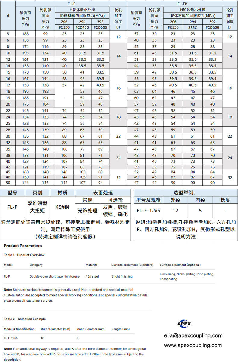
| Parameter | Specification |
|---|---|
| Product name | FL-F Thin-Wall Locking Assembly |
| Product type | Shaft-hub locking assembly |
| Design | Thin-wall taper type, according to supplied description |
| Material | 45# steel |
| Manufacturing process | Heat-treated forged steel, according to supplied information |
| Fasteners | High-strength tightening bolts |
| Connection method | Mechanical clamping |
| Available model references | MLR5×12 to MLR28×39, as listed below |
| Backlash | Described as backlash-free; confirm model-specific data |
| Installation | Bolt tightening according to manufacturer instructions |
| Customization | Available subject to technical review |
| Typical application | Industrial machinery and power transmission equipment |
Important: The exact dimensions, rated torque, allowable axial load, tightening torque, bolt grade and maximum rotational speed have not been provided. These values should be confirmed for each model rather than estimated.
Available Model References
The following model references were supplied for this product:
| No. | Model |
|---|---|
| 1 | MLR5×12 |
| 2 | MLR6×12 |
| 3 | MLR8×15 |
| 4 | MLR10×18 |
| 5 | MLR12×20 |
| 6 | MLR14×22 |
| 7 | MLR15×23 |
| 8 | MLR16×24 |
| 9 | MLR17×25 |
| 10 | MLR18×26 |
| 11 | MLR19×27 |
| 12 | MLR20×28 |
| 13 | MLR22×32 |
| 14 | MLR24×34 |
| 15 | MLR25×34 |
| 16 | MLR28×39 |
These model references are reproduced from the supplied product information. Please confirm the relationship between the MLR models and the FL-F product designation before publishing the table as an official series specification.
Applications of Thin-Wall Locking Assemblies
Depending on the selected size and rated performance, thin-wall locking assemblies may be used in compatible shaft-hub connections for:
CNC machine tools and automation equipment
Industrial transmission systems
Packaging and food-processing machinery
Textile and printing machinery
Material handling equipment
Mechanical engineering systems
Pulleys, sprockets and other compatible hub-mounted components
The correct locking assembly should be selected according to the shaft diameter, hub dimensions, torque requirements, operating speed and installation conditions.
How to Select the Right Thin-Wall Locking Assembly
Before ordering an FL-F thin-wall locking assembly, check the following:
Shaft diameter: Confirm the actual shaft diameter and its dimensional tolerance.
Hub dimensions: Check the available hub bore, outside diameter and installation space.
Torque requirement: Provide the normal operating torque and any starting or shock loads.
Axial load: Specify any axial forces that the connection must withstand.
Rotational speed: Confirm the required operating speed.
Installation dimensions: Verify the available axial and radial space.
Fastener requirements: Confirm the tightening torque and installation procedure for the selected model.
Operating environment: Specify temperature, moisture, dust and any corrosive exposure.
Model compatibility: Confirm whether the required model is FL-F, MLR or another designated series.
Customization: Provide a drawing or sample if a standard size does not meet your requirements.
Providing these details helps identify a suitable locking assembly and reduces the risk of installation or compatibility problems.
FL-F Thin-Wall Locking Assembly Manufacturer – Apex Coupling
Apex Coupling supplies industrial power transmission components and supports customized manufacturing according to confirmed technical requirements.
We welcome inquiries from machinery manufacturers, distributors, equipment integrators and industrial maintenance buyers looking for shaft-hub locking solutions.
For a quotation, please provide the model number, shaft diameter, hub dimensions, required quantity and application details. Technical drawings are recommended for non-standard requirements.
Contact Apex Coupling
Website: https://www.apexcoupling.com/
Email: ella@apexcoupling.com
WhatsApp: +86 13437856962
Frequently Asked Questions
What is a thin-wall locking assembly?
A thin-wall locking assembly is a mechanical component used to secure a shaft and hub through a clamping connection. Its compact design can help save installation space in compatible power transmission systems.
What material is used for the FL-F locking assembly?
The supplied product information specifies 45# steel. Confirm the final material grade and heat-treatment requirements for the selected model.
Does the locking assembly require a keyway?
A clamping locking assembly can transmit torque through contact pressure and may not require a traditional keyway. Confirm the shaft and hub design and the selected assembly’s installation requirements.
How do I choose the correct model?
Confirm the shaft diameter, hub dimensions, torque, axial load, operating speed and available installation space. Provide a technical drawing if possible.
Can Apex Coupling supply customized locking assemblies?
Customized supply may be available according to the design and manufacturing requirements. Send the dimensions, technical drawing and application details for review.
Rotex Equivalent Coupling, Jaw Coupling Spider, Steel Motor Coupling, Elastic Flexible Coupling, Polyurethane Spider Coupling, GR/GRS Coupling.
Product Show
thin wall locking assembly